Chapter 11 – First Floor Framing
Phase III
The three phases of the framing of the first floor are more based on my mental picture of how to raise the frame than any aspect of the frame itself. I envisioned a central box as a sort of foundation, something good and solid to build upon and use as a sort of central crane. The four extensions from the central box are arms, firmly attached to this foundation, that extend its reach to the edges of a new box. The corners are simply connections of the extensions to form a new and larger box. In theory, one could continue this process, outward to any size box. The final frame, if one doesn’t contemplate the splines, looks just like a bent raised timber frame structure. Once I had found a way to use the tools and materials that I had at hand, the three phases of construction were simply repetitions of the previous process incorporating small improvements that I discovered either by plan or by accident. The framing of the first floor was practice for the same process, another story upward in the loft, just as the basement was practice for the first floor. While I was building the basement, I kept in mind that the first floor would have no solid concrete wall to rely on. While I was building the first floor, I kept in mind that the loft would have no floor to stand on. As for the peak, I assumed that by the time I got there, the practice in the basement, first floor and the loft would provide all of the knowledge and skills that I would need.
The winter of 1997 was a vacation from Colorado! Our first grandchild was born and a flock of birthdays and holidays were celebrated. I made plans and lists, packed things that I wanted to have in Colorado, visited everyone I knew in Pennsylvania, made sure that Keith knew what timbers I needed him to cut and worried about the tarp and apartment in Colorado.
In February of 1998, Linda and I took a vacation to Colorado. When we got there, the tarp was still firmly in place and the apartment was just as I had left it. However, finding that the cistern was empty, I knew that a leak had developed. I had the solid PVC connection replaced with a rubber connection to solve this problem. No matter how firmly a cistern is planted in the ground, the process of filling it causes it to move enough to break a solid connection. Once our vacation was over, Linda went back to her job in Pennsylvania and I got back to my job in Colorado.
I started the framing of the corners with the southeast corner of the house, the kitchen, and then the northeast corner, the bedroom. This seemed like a good plan because these two corners were only a couple of feet off the ground. I figured that the practice I would gain near ground level would come in handy when I got to the west side corners whose edges were ten feet off the ground. I tried to make sure that the building process did not require me to step off the decking and onto the ground since the western corner posts had no ground to step off onto!
The raising of corner framing was very similar to the raising of the extensions from the central box. The existing attachment points for the beams (the extensions) had splines on which to rest one end of the beam while the corner post was leaned outward far enough (about four inches) for the beam tenons to be inserted into the post mortises. I now knew that the holes in the decking in which the post was inserted worked very well preventing the bottom of the post from moving. The only trick was to keep from tipping the post out too far. To make sure that this didn’t happen, three ropes were attached to the top of the post, two to the nice solid extension framing and one away from the corner attached to some heavy object, such as my truck. This third rope should be long enough so that if the other two ropes failed or the solid extension for some reason fell down, the falling post would not hit the truck! All of these ropes were tied with taut-line hitches so that the tension on any or all of them could be adjusted as necessary to tilt the post and bring it back into vertical.


I never did come up with a way to gracefully raise a single post without just picking up the end and tilting it into its deck hole. Sometimes, I didn’t quite get it in the hole and did a little dance with it. I did however carefully measure the lengths of the two ropes attached to the top of the post so that once I lifted the post upright; the two ropes would keep it from falling over in the other direction. The third rope was also already attached at the top of the post so that I could quickly attach it to a heavy object. With the length of the first two ropes carefully adjusted, pulling on the third rope would not pull the post over. The 10-foot length of the posts was also handy. I could attach these three ropes to the top foot of the posts and they would not interfere with the raising of the beams since all of the beams attached at the 8-foot high level of the post.
This phase also took longer because the parts were not precut, but rather, cut in the basement workshop, as I needed them. As I expected, this cut and assemble method went much better. The joinery was cut and assembled within days instead of months and did not have the chance to change shape. This method also resulted in my day-to-day projects changing so boredom did not set in, but the time between repeating the process was short enough that I did not forget what I had done before. As before, when the weather was obnoxious (which is not very often here in paradise) I simply turned my attention to improving the nice warm and comfortable apartment.
I should mention that there were also the more mundane, day-to-day projects going on as well, such as making meals, grocery shopping, washing clothes at the laundromat (where there was a phone to call Linda), braiding a rug and visiting with curious neighbors that stopped by to chat. My most frequent visitor was Carl, who was the self-appointed “make-sure-that-Michael-hasn’t-killed-himself” visitor. One bright sunny afternoon, I was in the process of raising the east beam of the bedroom wall. Carl drove in the driveway and stopped his truck within a few feet of the edge of the house. He sat in his truck while we chatted, and at some point I asked him if he wanted to help. “Oh no, if I help, then you won’t be able to say that you built this yourself!” That was true, and I didn’t really want any help anyway. Carl is also the person who, after the basement was covered and knew what the rest of the plan entailed, suggested that I cover the deck with dirt and plant grass. “This apartment is plenty big for just you and Linda!” That too, was true, but I didn’t listen to that advice either.
 In todays video, the bedroom corner framing will be raised. The east side beam on the sawhorses in the workshop will be raised first. The beam for the north side is on the cart, on its way up the hill. I need to cut the brace mortises in the two already raised extension posts. This is the hard way to cut brace mortises and not a good plan. With the brace mortises cut and the post hole in the deck revealed, I am ready to raise the beams. The north beam is raised into position with the right side brace tenon in its beam mortise and the beam tenon in its post mortise. The left side of the beam is in contact with the post and ready to slide down into the housing and onto the brace tenon and post spline. The close-up shows the beam spline mortise that will be lowered onto the post spline. My initials are in the post housing. Slowly lowering the crane arm, the left side of the beam slides down into position. With the beam lowered into position, another come-along pulls the assembly tightly together. Next, the summer beam that drops in the dovetailed mortise in the east beam is installed.


In the daylight basement shop, twelve 6x 8 joists were cut to length and dovetails carved at each end. Using the crane, they were lifted above the beams and lowered into their dovetailed mortises.
The raising of the northwest and southwest corners was done next. The procedure was the same as the northeast corner above, except that there are no joists. Not having anywhere to stand outside the edge of the frame proved not to be the problem that I expected, it was something different – naturally – it’s always something. Again, I didn’t have the foresight to pre-drill the peg holes. To be more generous to myself, it seemed like a good idea at the time to drill and peg the beams after they were raised and tightly in place. Before describing this part of the raising, the post joinery should be explained.
This frame design features all of the top surfaces of the horizontal beams on the first floor level at the 8-foot 10-inch height above the floor. Having never designed a timber framed building before, and certainly not experienced enough to have a firm grasp of all the details; I was concerned about having the entire loft floor surface at the same level across two bays and having beams at that level around the edge of the loft level as well. It seemed to me at the time that this requirement could not be satisfied by the traditional framing methods. In hindsight, this requirement was pretty silly and traditional framing methods would have worked just fine. I seem to have invented a problem and then invented a solution, neither of which was necessary! On the bright side, my solution worked very well and looks beautiful!

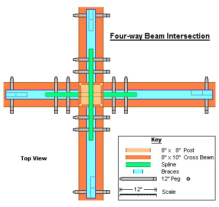 Traditional timber framing does not allow for four beams to meet a post at the same height without using posts that are very wide at the top. The reason that a large post top is needed is that once two of the beams have been pegged on either side of a square post, the first two beams have covered the pegging sites for the tenons of the other two beams. The joining of four beams at a post without using a very large post top is accomplished in this frame design with the use of two splines that cross within the post, one spline along the top of the two bent beams running one direction and one spline along the bottom of the two summer beams running the other direction. In this fashion the splines serve as four tenons that are joined to the beams rather than the post. In fact the spline is not pegged to the post at all but floats inside its slot. When I assembled the central stairwell box, the eight splines (two at each corner) were pegged to the beams leaving the other end of the splines sticking out to receive the eight extension beams that were raised later. What was actually holding the free standing central stairwell box together was the sixteen braces that were pegged to the four top beams and the four corner posts. The four posts between the four corner posts are decorative, with the exception that two of them are used to support the landing for the stairway to the loft.
When three beams meet at a post at the same level, only one spline is used. This configuration occurs in eight locations of this frame design, once at each end of the bent #2 and bent #3 first floor bent beams, and once at the ends of each of the four summer beams that extend from the central stairwell box to the outside edge of the frame; in other words, at the ends of the extensions of the central stairwell box. The alternative to this spline technique would be to have tenons at the ends of both 6x10-inch bay beams at the outside of the frame. Both of these tenons would need to be pegged from the outside of the post with short pegs to avoid driving the pegs into the backside of the bent beam housing. The outside bay beams are 6 inches wide meeting an 8-inch wide post. This leaves two inches of exposed post for the pegging of the perpendicular bent beam tenon. This is not a problem as long as the beam is pegged before one or the other bay beams are set in place. The spline is located at the lower edges of the bay beams with the top half of the beams housed into the post. The spline mortise is 4 inches deep, 1 1/2 inches wide and 11 inches long. The spline itself is 5 inches wide, leaving 1 inch exposed below the bottom of the beam. This exposure not only looks nicer, but it increases the amount of wood in the spline. With an 8-inch post, the total spline mortise is 30 inches long. I cut the splines about 1/4-inch short to allow for post shrinkage and to insure that the spline would not interfere with the assembly of the outside corners of the frame. The three braces are three different sizes, as they are in the four-way intersection, 24 inches in bay #2 and between the summer beams, 30 inches in bay #1 and bay #3 and 36 inches in the bents. This allows the three brace mortises to be at different locations on the post. If two or all three braces were the same size, two or three mortises would be at the same point on the post on two or three sides, dramatically weakening the post.


 I pegged the spline to the 6x10-inch bay beams in the extension sections when they were raised, again leaving the other end of the splines sticking out to receive the eight beams that connect to the four corner posts that were raised later. Since I pegged the braces in the extension section, the two posts were locked in place by the braces. Then, when I raised the corners, I wrapped straps around the corner post and the two extension posts and pulled the corner post inward creating a tight fit of the beams attached to the corner post and resting on the un-pegged splines. Once the two beams were tight between the two extension posts and the corner post, I pegged the beam tenons in the corner post. Then the two splines extending from the extension posts were pegged to the two beams. Pegging the four braces in place locked the entire assembly together.
The four two-way intersections at the corners of the frame do not use a spline. The 8x10-inch bent beam that meets the 8x8-inch corner post is pegged just as the bent beams are for the three-way intersection. The 6x10-inch bay beam, instead of being splined, is also pegged to the post. The bay beam mortise must also be pegged to the post from the outside of the frame. Since this peg will hit the housing of the bent beam if driven in too far, I cut it to the right length before I pounded it in. The lower peg for the bay beam brace must also be driven in from the outside of the frame since its position is very close to the side of the bent beam brace.
 On April 12, 1998, the first floor framing was done. It had taken two months to finishing framing the four corners starting from the finished central plus assembly. Before I assembled any parts of the frame, I applied tung oil to the joinery areas, including inside the joints. I quickly learned to avoid oiling the center of gravity areas of the timber that I used to wrap straps around. The tung oil makes the timbers very slippery and the strap slides around much too easily. Once a section of the framing was pegged, I oiled the rest of the section.


 Oiling the timbers also exaggerated the color differences of the three species of oak timbers that I was working with. Most of the timbers were made of red oak that, when oiled, turn golden brown. The rest of the timbers were mostly white oak with an occasional pin oak. It is hard to tell what kind of oak a weathered timber is, they are all kind of gray looking. It was easy to tell when I started working with a white oak timber, white oak was much heavier than red oak and it was as hard as a rock. The color of oiled white oak varies from almost white to chocolate brown, even within the same timber. The pin oak timbers were also easy to differentiate once I started working with, them they smelled bad. These pin oak timbers have the most grain character and large color variations within the timber.
As time has passed, to the average person, all three kinds of oak timbers all look the same golden brown. To me, after having examined each timber for its suitability for a particular frame member, moved it from the storage pile to the sawhorses to the raising site and then lifted it into place, planed, sanded and carved joinery into it, I know each timber intimately. To me, each timber is a unique oak tree that I know very well and am proud to have as a part of my home.
No comments:
Post a Comment