Chapter 12 – Loft Framing
Phase I
The loft framing was done in two phases. Phase I is during the seven weeks between the finishing of the first floor framing and the first of June. I then returned to Pennsylvania and it took about a month to arrange for the third and final flatbed truckload of oak timbers and boards to be delivered to Colorado. In the middle of July, Linda and I rented a moving truck, loaded it up with more furniture and followed the flatbed to Colorado. While we were together in our apartment, we re-arranged the furniture and stored the furniture that wouldn’t fit in the apartment under a tarp in the corner of the daylight basement. Phase II of the loft level raising began after Linda went home and was completed on September 16, 1998.
As usual, my documentation begins after the first steps of the project are done. I was more occupied with how I was going to safely accomplish this phase of the project than photographing the process. Perhaps I had documented enough ”oops” that I didn’t want to do it again!
My problem solving technique involves the extensive use of the process known as “sleep on it”. If the problem is complicated or new enough, this “sleep on it” process can be very long! I usually wake up with a notion of a solution to the perceived problem and spend the rest of the day fitting this solution into the existing grand plan. This often leads to another problem to sleep on, starting the process all over again. Sometimes I even resort to finding a book on the subject or asking someone who might have some ideas on the matter. In due course, a plan worth testing without any foreseeable “gotchas” evolves.
My high school English teacher required as part of the course that we keep a journal, and turn it in once a week so that he could make sure that we actually wrote something. I think his plan was to provide penmanship and authorship practice. Since high school I kept other journals from time to time that I have found useful for one reason or another later on. While building this house, I made tons of drawings and lists, took many photos, filmed several hours of what I thought were significant events, but did not write one line in a journal. I certainly wish that I had done so, now that I am trying to remember what happened several years ago! I mentioned this to Linda and her response was that I was probably so tired at the end of every day that writing in a journal was not an option. Perhaps.
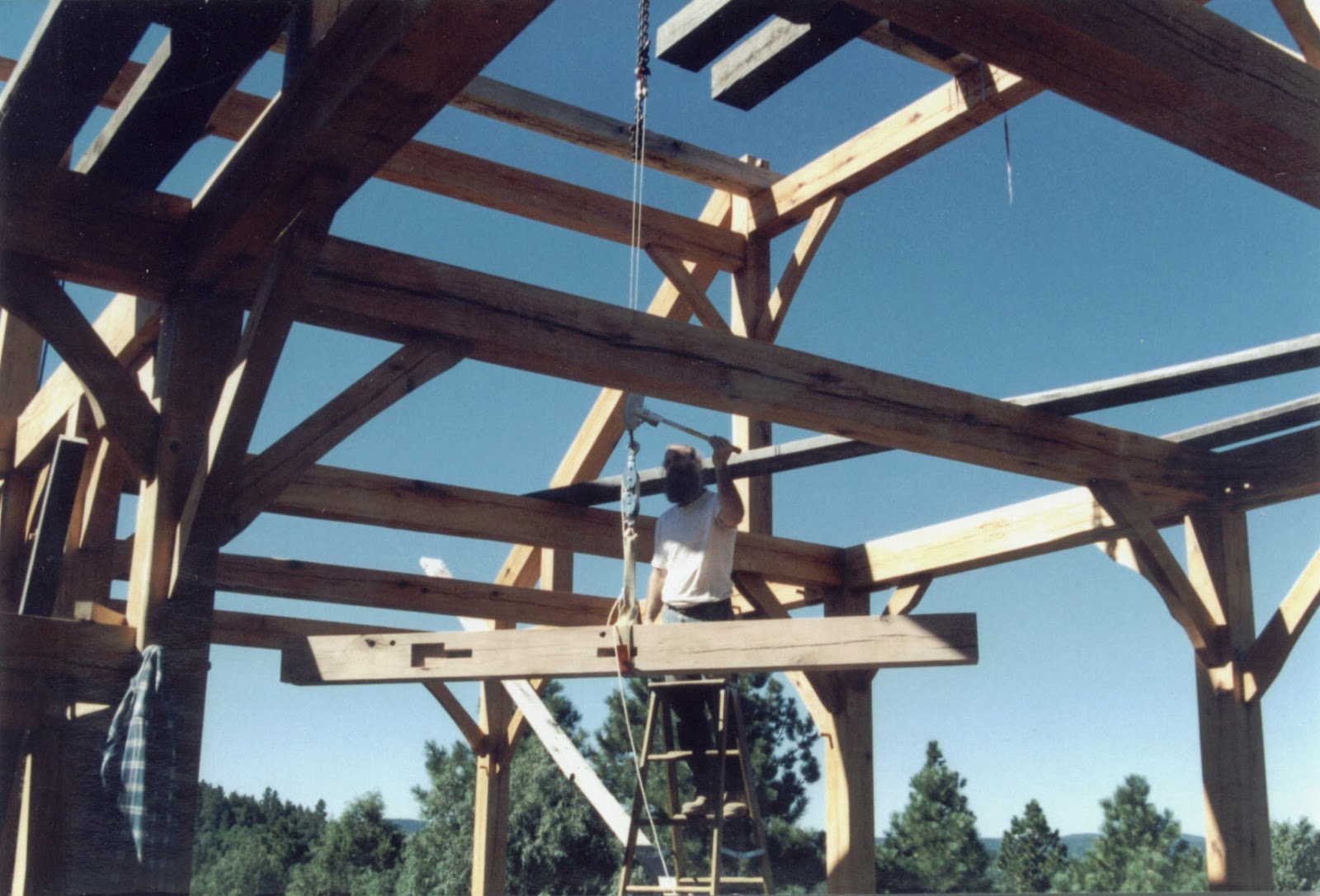
Since it took several days in the basement to create the posts, beams and braces for the first section of the loft framing, I had several nights to sleep on the plan to raise them on top of the existing first floor framing. At some point, it dawned on me that, contrary to my notion that it would be just like the raising of first floor level only higher up, there was a big problem that needed to be solved. The first floor posts had a very convenient hole and peg in the deck that insured that they would be guided to and held in their proper location as they were being raised into position with guy lines as an insurance policy. All that I had on the top of the existing first floor framing was a nice slippery eight-inch wide beam to stand the posts on with a big drop-off on either side. Unlike raising a post on the deck, dancing with the post to move it to its hole was not going to work.
As I was creating the loft framing, it also occurred to me that this structure was very big. It was the same shape as the post, beam and brace structure at the ends of the first floor extensions, but the beam was twice as long. Even with this 250-pound weight difference, I could probably raise it like I did the extension ends if I could solve the post bottom-anchoring problem. On the other hand, this longer beam made it the same as the corner structure, so perhaps I could raise it like I did the corners. However, the raising of the corners had the advantage of one of the end posts already being firmly set in place. All I had to do in the corners was raise one post, set it in its deck hole, anchor it temporarily in place with guy lines and then lift and install the beam and braces in between. I could not come up with a plan that would insure that I could lift two posts into position on an 8-inch wide beam, make the beam braces stay put in these posts and make all of this stay put while I raised a 16-foot beam between them. One oops, bump or gust of wind could send these pieces crashing to the ground, or worse, through the deck and into the basement! If these raising problems were not enough to scare me to death, the fact that the only place that I would have to put my feet would be the tops of the 8-inch wide first floor beams 9 feet above the decking should have. I tried to stay focused on the physics problem and ignore the scariness of the situation.
 One day, a solution to the post bottom-anchoring problem occurred to me. What I needed was a peg of sorts that would catch the bottom of the post and keep it from falling off the edge of, or sliding along the length of the beam that it was lying on as I pivoted it from horizontal to vertical. This peg of sorts was a tenon shaped rectangle with one corner cut off. The square end was inserted in a mortise in the beam where the post belonged and the cut off corner faced away from the bottom of the post with a similar mortise cut into its bottom. As the post was raised from horizontal to vertical, the block caught in the hole in the bottom of the post. The cut off corner allowed the post to pivot onto this block as it pivoted towards vertical. I made a drawing of the concept and even made a small model to test out the plan. The only way to know that this was going to work was to go for it.
I used this plan to raise the first loft post and beam assembly. First, I assembled the two posts and their beam and braces horizontally. The post bottoms were then aligned with my blocks. Several straps were attached end-to-end and stretched from the loft post and beam assembly to the far side of the frame with a come-along attached to the beam. I lifted this assembly with a pair of come alongs attached to the far side of the frame. Once the first come-along had gone from fully extended to as short as it could get, a second come-along was necessary to continue the lifting process. The second come-along was strung from one of the strap loops to another loop further back along the strap. Shortening the second come-along shortened the strap length and continued the lifting of the assembly toward vertical. Knowing how I raised the rest of the loft framing (with the crane), this method was definitely the hard way and no doubt put a lot of stress on the beam that I used to pull from, not to mention the blocks that held the post bottoms in place. As I think about this process now, I am a little amazed that this method actually worked. It does indicate the solidity of the first floor framing though.


To get the exact length for each rafter, I used a stick with the rafter angles cut at each end that was exactly the geometrically correct length. I knew that this stick length would be too short because most of the posts are a bit smaller than 8 inches wide. Placing the stick between the rafters, I measured how short the stick was to fit perfectly and added that length to the stick length. With these dimensions, I retrieved four of the 14-foot long 8x10-inch timbers from the timber pile, planed and sanded them, and drew the joinery on them at both ends.
At this point, the words of my mentor rang in my ears. Having never cut a bird’s beak in Ed’s shop, I recall asking him how you cut this kind of joint. His response was that by the time I got to the cutting of this type of joint, I would know what to do! This was not the answer that I wanted to hear at the time but it did seem like a problem that was really far in the future, so I did not worry about it much. Now was the time to worry about it! I used the end of my longest timber and added another bird’s beak drawing to the spare wood at the end of the timber. I used a post cutoff to create the mortise that was at the tops of the outside posts and another post cutoff to create the mortise that was at the tops of the queen posts. This practice bird’s beak joint came out just fine and fit fine in my model of the post top too. Just to be on the safe side, I cut a practice top end of the rafter as well and it too fit the model of the queen post top. Ed was right, the practice of the last few years made it clear how to cut this fancy joint. I cut off this practice bird’s beak joint and proceeded to cut the four rafters that fit up in the frame perfectly. We still have that cutoff bird’s beak model; I’d like to think that someone would find it fascinating and ask me about it, but mostly, we use it to weigh down plastic lawn chairs to keep them from blowing away in the spring winds! Actually, there are a bunch of these practice joinery stubs lying about the house; they make pretty good doorstops and book ends too.


As usual, the video record is of the raising of the second rafter with the first rafter already in place. There is also one more action packed video documenting the loft framing, Phase I. The beginning of this video is of the raising of the second loft bent beam. Although the background scenery is better because the camera is one story higher, the action is not much different than the taped raising of beams on the first floor.
Once I got to the loft framing, my new, improved gin pole became useful. The original gin pole was a 10-foot long 2x6-inch board. The new pole is 18 feet long by mortising and bolting another 10-foot long 2x8-inch board to the original pole. Though unwieldy, this pole was invaluable throughout the rest of the project.


The above story of the raising of the rafters skips over an important part of the project, the timber elevator. To raise the roof structure, each timber had to somehow get from the basement workshop to the first floor and up to the loft level. I had lots of practice getting timbers to the first floor. Fortunately, the frame structure provided a way to raise them to the loft level. I use the word “fortunately” because the open (no joists in the way) west part of the frame was designed that way simply to provide open space above the dining room and living room areas. Conveniently, the space in the center of bay #1 was big enough for a 16-foot long timber to fit through the opening crosswise. The center opening is 8 feet wide and 14 feet, 8 inches long, making the cross distance of the opening 16 feet, 8 inches long. The rough timbers that I used for scaffolding barely fit through this opening, but the finished timbers fit through this opening easily. With this handy coincidence in mind and while I had the crane situated in this area, I lifted two 16-foot long 6x8 timbers to lay across the top of the bay #1 loft structure that I had just built. After strapping the ends to the bent beams, I wrapped a chain around the center of the timber that I made sure was in the center of the opening and left the end hook of the chain hanging down far enough that I could reach it from loft scaffolding boards without a ladder.

Leaving one timber up there would have been enough to create the elevator that I had in mind. However, I was contemplating that eventually I would need to raise two king posts and the peak purlin above this timber. I would need at least two timbers up there just to stand reasonably comfortably up at that level - 18 feet above the deck - in the wind - with nothing to hold on to. I was not at all comfortable with this prospect, but I decided that I better get used to the idea. In fact, at this point, I had no notion of how I was going to raise the king posts and peak purlin and, for the moment, avoided wandering about on top of these timbers any more than necessary!
It was time to suspend the loft framing project and head to Pennsylvania once again. I always drove my truck and took different routes back and forth. Flying long distances to get somewhere quickly is not for me. The views from an airplane are certainly unique, but I would much rather see and experience the world from ground level.
No comments:
Post a Comment