Chapter 11 – First Floor Framing
Phase I
While trying to reconstruct the process of building this house, I have been relying on my photo albums and the memories sparked by those old photographs. The “1996 – 1997” album begins with photos of the first flatbed trailer loaded with timbers for the decking. All of the photos of the deck construction process, which was completed on August 1st of 1996, came from this album. When I got to the end of this album I found a few photos of the cutting of the central “plus” in Linda’s garage in the winter of 1996. The next photos of the house are winter 1997 photos of the already assembled central “plus” of the first floor. I realized that I had no photos of the central “plus” construction process. In fact, the second flatbed trailer, loaded in September of 1997, must have been so “ho-hum” that there are no photos of that either. Much to my dismay, I realized that in September of 1997, I had decided to start documenting the building process on videotape and had no photographs.
Fortunately, modern technology has a solution to this dilemma. A video card installed in this computer allows me to watch these videos and create images of the tape with a click of the mouse. The down side is that the photographic quality is worse than a camera. However, the audio part of the tapes is very enlightening. On the tapes, I was explaining what I was doing at the time and sending the finished tape to Linda in Pennsylvania. Watching these tapes is a lot like watching paint dry. I often put the video recorder on a pile of timbers, aimed it at the project, and went to work. Without a catastrophe to add excitement, the process of raising timbers is very slow, tedious and boring to watch. I did do some step-by-step filming that cuts out the tedium and adds explanations for the photos. These tapes made me realize how much my memory had forgotten! I also realized how much I learned in the building process. This was definitely a learn-as-you-go project. During one of my taping sessions, I filmed the raising of a beam and two braces that connected to the central box and one of the outside wall sections. With a flamboyant, “tah-dah” I proclaimed the process a success and picked up the camera to do some close-ups. Much to my horror, I realized that I had installed one of the braces backwards. While reviewing this tape, six years later, I heard myself say, “I guess I should tape my “fubars” as well as my “tah-dahs”. Reviewing these tapes was informative and entertaining. I often found myself mumbling, “what are ya doin’, ya dope?” Another problem with this taping scheme is that either the battery died or the tape ended before I got to a “tah-dah”.
My video taping of the construction process begins with my using the covered front half of the basement outside of the apartment walls as a workshop. I set this area up similarly to the work area in Linda’s garage, minus the wood stove. It was really nice to be able to go from my nice warm apartment to the workshop and back again with ease.


This time, I had unloaded the truckload of timbers with a little better foresight, putting the various timber bundles closer to where they would be needed. The small parts such as braces and splines got stored under cover in the workshop, the finished parts and timbers that I would not need for a while were stacked on either side of the deck and the timbers that I needed to work on yet to create the central “plus” of the frame were piled in the driveway outside of the workshop.
Once I got daily life organized in the apartment, I spent every available daylight hour working on assembling the frame. The first thing I needed to do was invent a way to get materials from the workshop up to the deck.
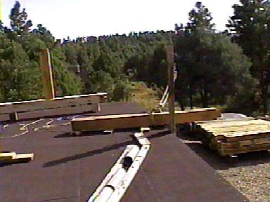
My first gin pole, used to support the sill beams across the daylight opening of the basement, is featured at the beginning of the first tape. I used this gin pole to lift timbers from the daylight basement workshop to the first floor construction site on the top of the deck. This method was an alternative to tedious process of wheeling timbers on the cart up the driveway hill. As it turned out, the gin pole and pulley system was fine for timbers less than 16-feet long. The 16-foot timbers, weighed 500 pounds or more, and were more than I could lift, even with my pulley. I was persistent though. Attaching the pulley line to the truck and driving down the driveway did pull the timber from the basement to the deck. Unfortunately, by the time the timber was near the top of the pulley, I was in the truck about 100 feet away trying to see what was happening in the rear view mirror. I quickly decided that this was a bad plan and went back to the cart method for the big timbers.


Before I could begin raising the pre-cut central stairwell assembly, I needed to establish the landing for the stairway from the first floor to the loft. Since the distance from the finished floor of the first floor to the finished floor of the loft was the same as the basement stairway dimensions, the support beam heights from the bottom of the posts were the same as the basement stairwell landing.
I really had fun with the movie making idea. Other than an occasional visit from Carl, one of the ranch residents who checked to see if I was still alive from time to time, I seldom saw anyone. The camera became someone to talk to! So, I perched the camera on a beam and turned it on and off between noisy sawing and drilling steps and described what I was doing. Perhaps I’m a frustrated teacher.
Once the stairwell posts had their landing beam mortises cut and the 4-foot long 6x8 landing beams had been cut out, I used the gin pole to haul them up to the deck surface for raising. To facilitate moving these posts around, I created what I called “railroads”. Along the outside edge of the workshop, I piled some 16-foot long beams on blocks that reached from the sawhorses to the gin pole. This allowed me to pivot the posts off the sawhorses onto the railroad. Instead of sliding the posts on these beams, I put short pieces of leftover PVC piping under the posts to serve as post wheels. With three pieces of pipe, I could always have two rollers under the post and move the back roller to the front end and continue rolling the post as far as I needed it to go. Up on the deck, I used long 2x4s laid on the deck as the railroad, beginning at the gin pole and leading to the raising site. I also kept another set of three piping pieces up on the deck for rollers.
Controlling the post during the process of raising it with the gin pole required at least one rope attached to the end of the post. I tied each end of a 1/4-inch hemp rope to each end of the post so that I could control either end if necessary. With practice, I only needed one end of the rope to get the job done.
Once all of the parts had been cut and delivered to the deck, I could reassemble them as I had done in Linda’s garage. My method for marking timbers was based upon their bay number and their facing direction. The bay number was chiseled in roman numerals (roman numerals are easy to create with a straight edged chisel) in the bottoms of the posts. Inscribed in the beam housings were the directions (N, S, E or W) that the housing should be facing.
Before any post could be raised, its base hole in the decking had to be excavated. Measuring from each edge of the deck I could determine about where the post should stand. Cutting through the rolled roofing and the tar paper I easily found the central peg and its redwood 8-inch square block imbedded in the decking. After cutting the roofing a bit larger than the edges the redwood block, a few whacks of a chisel with the grain of the redwood split these blocks and after the pieces were removed, my neat 8-inch square post hole was revealed. I cut the roofing larger than the post hole to avoid marring the post with tar. Once the post was installed, I used urethane foam to seal the crack between the post and the decking edges. The foam created a waterproof seal by expanding up the side of the post and sideways over the edges of the roofing. Once the foam was dry, I beveled the edges so water running down the post would be deflected onto the roofing. Several years later, when the frame was dried in, this foam was easily scraped and sanded off the post and out of the cracks.
I began the assembly of the central stairwell frame at the landing corner (northwest) because the landing beams would help to hold the posts upright and straight. To begin, I laid the center post and the north center post on 2x4s and inserted the landing beam in its mortises, strapping the unit together with a 2-inch orange ratchet strap. I then positioned the engine crane perpendicular to the assembly and raised the crane arm. This didn’t go quite as easily as it had when I had done the same thing for the “H” assemblies of the basement daylight wall. Unlike the “H’s” in the basement, which had a crossbeam above the center height of the posts, the landing beam was about in the center of the beam height. Therefore lifting the assembly simply raised the unit rather than pivoting it at the bottom of the posts. I solved this problem by sliding the crane backward until the post bottoms caught on the pegs in the deck and kept the backward tension until the unit was past halfway raised. Nudging the posts backwards settled the holes in the bottoms of the post onto their pegs.


Here are examples of watching the video of myself and asking me what I am doing. The brace peg holes for the above posts were pre-drilled. The crane should have been attached to a line running through those peg holes. Below, I raised the next post with its landing beam in place as a “counterweight”. Yes, it was indeed a counterweight, but standing the post up, and holding it up with the crane while installing the landing beam would probably have been easier.
The above sequence of events from the first video occurred over the course of five days. The next tape begins with the four landing posts and beams already assembled. What was skipped was the raising of the fourth corner post and the installation of the other two landing beams. By the end of the second tape, four days later, the rest of the central stairwell box is completely assembled.


The next parts to be raised are the two 8-foot long beams connecting the tops of the standing posts and extending to the other corners of the stairwell box. With these two beams in place, the raising of the corner posts under the ends of the two beams is simply a matter of standing the posts up in their correct position and putting the braces in place at the same time. Once the beam and its braces were in place on top of their posts, the splines could be inserted in their slots.
By now, I was beginning to realize the raising height limitations of my engine hoist. Even with a block under the beam to take up some of the strap length, making the crane hook as close as possible to the top of the beam, the crane could not quite raise a 10-inch thick beam to the top of an 8-foot tall post. The distance from the bottom of the wheels to the bottom of the hook is about 8 feet, 8 inches. Even with the hook as close to the beam top as possible, raising a 10-inch beam to the top of an 8-foot post left the crane lift about two inches short. I compensated for this 2-inch shortage by mounting the crane on 2-inch thick boards to serve as wheel runners. These runners not only allowed the wheels to roll more easily than they did on the roofing, but they also kept the wheels from damaging the roofing. The down side to this plan is that it is hard to keep the wheels on the runners unless the runners are very wide. Since my widest runner boards were about 8 inches wide, I was constantly fighting with the crane wheels and runner positions to keep the crane on the runners and the beam in the air heading where it needed to go. Complicating this plan some more is the fact that the front wheels are wider apart than the rear wheels. This meant that the runners had to be set up in a V shape and if the crane had to move too far along the runners, the separation of the back and the front of the V had to be adjusted as the crane moved forward. I soon learned to position the crane, the runner boards and the beam that it was lifting as close to where they needed to be as possible before I started the lifting process.
Another quirk to an engine crane that needed to be dealt with is that as the crane arm raises, the tip of the hook arcs backward. So, if you start raising a beam directly under where it needs to go, by the time it is 8 feet high it is almost 2 feet farther back from where it started. This means that, in most cases, the crane will need to be moved forward at least 2 feet as the lifting progresses. Adding a safety factor to keep the beam from hitting the existing assembly, the crane actually needs to be able to move forward about 3 feet from the start of the lifting process to where the beam on the hook is in its final position.
A third crane lifting setup-up problem is the positioning of the strap that the hook grabs. Ideally, the strap is positioned at the beams center of gravity. That way, as you raise the beam, it stays level. This central strap positioning is not always possible. In the case of the two beams that I now needed to raise, there is a post mortise in the center of the beam. Wrapping the strap around the center of the beam to raise it level would make it impossible for the center beam mortise to fit into the tenon at the top of its post because the strap would cover the mortise. To solve this problem, I positioned the strap on the side of the beam mortise and strapped blocks of wood to the top end beam to serve as counter weights to keep the beam level as it is raised. Initialy, I used a bar clamp to hold the blocks on the top of the beam. If this bar clamp is bumped, it tends to come loose and fall off. A better method is to strap the blocks to the top of the beam.
Another lifting problem is the ability to control the two ends of the beam as it is being raised from my cranking position at the back of the crane. The beam tends to start swinging back and forth, especially if I get too energetic and crank the beam up too quickly. Invariably, the wind also wants to participate in moving the suspended beam, usually rotating it out of parallel with my plan. Therefore, I always attach a rope to each end of the beam, leading back to my cranking position, so that I have some control over the suspended beams movement.
This all probably sounds like a lot of trouble to raise a beam. Since I was committed to my engine hoist, raise one-beam-at-a-time plan, these are all just problems to solve that are part of the process. Solving these problems at deck level turned out to be very important. It was still pretty scary raising the peak purlins with the crane standing on scaffolding attached to the frame, 16 feet in the air, in a hefty breeze, but at least by then I had lots of practice and knew what to do and what was going to happen.
The next parts to be raised are the two 8-foot beams connecting the tops of the standing posts and extending to the other corners of the stairwell box. With these two beams in place, the raising of the corner posts under the ends of the two beams is simply a matter of standing the posts up in their correct position and putting the braces in place at the same time. Once the beam and its braces were in place on top of their posts, the splines could be inserted in their slots.
The first thing to do was move the beam from the finished timber pile next to the deck to its raising position. Two boards lying on the deck, starting at the timber pile and leading to the raising site served as railroad tracks. With a PVC roller waiting at the end of the railroad track, I slid the beam from the pile onto the roller. Sliding the back end of the beam on the pile supports, and rolling the front end forward down the tracks, the beam rolled onto the waiting next roller. Moving the rear roller to the front as the beam rolled along brought the beam to its raising position.
With the crane on its runners, slightly to the left of the center post, I slid the beam onto blocks to position it above the level of the crane legs. Next, the strap is wrapped around the beam, also slightly to the left of its center. With a few blocks piled on the left end of the beam to serve as counterweights, the beam was ready to be lifted into position. Beyond the ease of rolling the beam into position, the railroad tracks and rollers being off the roofing kept the rollers from picking up the grit of the roofing and smashing it into the beam surface. Since the PVC rollers are very slippery, rotating the beam on the roller was almost too easy and the beam had a tendency to slide off the roller onto the roofing. I found it best to transfer the beam to a block under the center of the beam before I tried to rotate it. With a few more blocks around the crane legs, I could slide the beam off the rollers and onto the blocks over the crane legs and into position.
I also liked to have the mortise peg holes pre-drilled. When it was time to install the pegs, the pre-drilled holes provided a good guide for the drill bit and the only wood that needed to be drilled out was the hole in the tenons. These holes also came in handy as places to firmly attach ropes.
The next timber to put in place was the northeast post. Since this post did not have to make a trip to the basement to have a landing beam mortise installed, it was sitting in the finished timber pile next to the deck. The post was rolled on the railroad to its raising position just as the previous beam had. Before the post could be raised, the hole in the deck had to be cleaned out and a corresponding hole in the bottom of the post drilled. Using ratchet straps to hold the two braces in position, I put the end of the post into its hole in the deck and lifted it the hard way. With a little wiggling, I got the brace tenon to go into its mortise in the post as the post went into position.
This was a crucial moment for the future logistics of this project. I discovered that the housing at the top of the post would not slide into the housing at the end of the beam. Two nasty things had happened to the joints since they were made and fit perfectly in Pennsylvania. The top of the beam had split a bit making the beam housing wider and the top of the post had shrunk making the post housing narrower. This not only prevented the housing from fitting together, but it misaligned the slot for the spline. Making joinery in Pennsylvania and assembling it in Colorado became a really bad idea.


What I had to do was lower the post back down to the deck and fix the joinery. I shaved the spline mortise in the top of the post back to its 1 1/2-inch width. Then, on the ladder, I shaved the beam housing back to fit the width of the post housing. Then I shaved the spline slot in the beam to align with the slot in the top of the post. This was not the last time that I had to adjust the pre-cut joinery, but it was the last time that I failed check the joinery fit before I raised the timbers.
The raising of the other two sides of the stairwell framing was accomplished just as the first two sides were done. After I made sure that the framework was square, I made and installed two short beams to connect the center post top to the east and south cross beams. These two beams, besides connecting the top of the center post to something, outlined the ceiling for the top of the basement stairwell that is also the floor of the loft in the corner of the loft staircase. When I was certain that the entire structure was square, I drilled out the holes in the tenons and pounded in pegs and slid the eight splines in the corners into place. Since the splines actually float within the post, I did not peg these splines until the adjoining beams were in place.
With this central stairwell box completed, the first phase of the first floor framing was complete. The next phase was to connect the central box to the outside wall framing with beams extending from the corner posts to posts at the outside of the frame. At this point, what was holding the center box together was actually the array of 2-foot braces since the tops of the posts were simply butted together and kept aligned with the splines. Bent #2 and bent #3 are formed with the addition of the beams running to the outside posts and the bents tied together by pegging these beams to the center beams with the spline that passes through the corner posts of the center box. The splines are cut 1/4-inch shorter than the long mortises that receive them. Once the bent is assembled and pulled tightly together, the spline can be centered in the long mortise and pegged to each bent beam.
No comments:
Post a Comment