Wednesday, May 8, 2013

Chapter 14 - The Finished Frame


Chapter 14 - The Finished Frame
I’ve read that traditionally, the completion of a timer frame is celebrated by nailing a pine bough to the peak of the frame. I recall considering this tradition and how I might abide by it. Cutting a Colorado pine bough and nailing it to a frame that was made from Pennsylvania oak trees just didn’t seem appropriate. I had no oak boughs from Pennsylvania and the local scrub oak didn’t seem appropriate either. For better, or for worse, I was interrupted before the frame was completed, the party of my neighbors watched me install the last purlin and by the time the champagne was gone, the pine bough tradition was too late and totally out of mind! This was not exactly a traditional timber frame and certainly not built in the traditional fashion, so maybe the tradition was not appropriate anyway. In many respects, it was more like launching a new ship. Carl even wanted to smash a Campaign bottle on the bow but wasn’t sure where the bow was or that we had enough Campaign to waste a whole bottle. In any case, the frame was done, the ship launched and Linda and I have been enjoying it every day since.


Chapter 13 - Peak Framing


Chapter 13 – Peak Framing
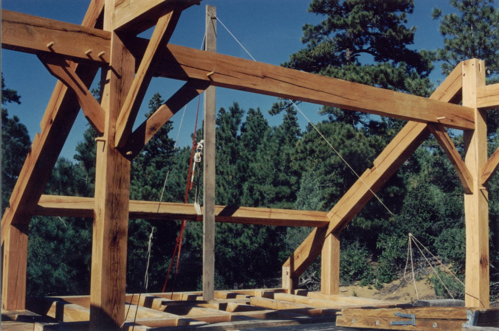
Now it was time for the truly exciting part of building my timber framed structure. This is the peak of the house, the highest point, and the place with the best view, the most wind and the longest trip to the floor! I spent some time at the tops of the queen posts before I started to get used to this elevated location. Evaluating the fit of the lower rafters at the tops of the queen posts was more to have a reason to be there than having any expectation that something might be wrong or need to be fixed or that any problem was even fixable. There were no joists to stand on or leap to and nothing overhead to steady my balance. The building of the peak was where all of the practice and experience would culminate in catastrophe or success.
 
Ridge Pole ground test
The first thing to decide was where to start. I started the loft level framing over the two outside bays and then connected the center bay timbers between them. I did that so that if the structure was out of plumb or square, I could make some adjustments in the center bay. Since I didn’t need to make any adjustments, this sequence didn’t seem necessary for the peak. Another consideration was that the peak assemblies were just a king post and a peak purlin, two legs and a crosspiece. This assembly would not stand solidly until the two upper rafters were attached to hold it up. The loft assemblies stood solidly without the lower rafters since they were four legged boxes. The biggest consideration though was the size of the assemblies involved. I felt more comfortable with the idea of starting with the smaller 8-foot wide assembly over the center bay rather than the 16-foot assemblies over the outside bays.me.
50 mile/hour wind survivor
Furthermore, I reasoned that the outside structures would be easier to raise if the inside king posts were already in place and well secured. That way I would only have to worry about the outside king post and its peak purlin instead of two king posts and a peak purlin all at the same time.

Ignoring the height above the ground, and the fact that my raising equipment would need to be set up on top of the loft timbers, the peak assemblies should be easier to raise because the peak purlin is not as high as the loft and first floor cross beams. The peak purlin is attached to the top of the king posts that are only 7 feet tall instead of the 8 or 9-foot height of the loft and first floor cross beams attached to 10-foot tall posts. Though this is simply an artifact of the geometry, this shorter structure seemed a lot friendlier.


Once I had rationalized that raising the peak was going to be no big deal, I cut the parts. Since I wanted the peak to be a focal point, and one would be looking at it from two stories below, I made the braces a bit larger than the other braces. These braces are the same length and shape as the other braces but are an inch larger in the width and thickness. This slightly larger brace size makes the roof structure appear more solid and obvious. The king posts also appear slightly larger than the other posts because the tops where the rafters and peak purlin meet it are 10 inches wide instead of the 8-inch width of the queen posts. This extra width is actually there to accommodate the mortise for the peak purlin in the center of the face of the king post. I made the king posts from 8x10 timbers and ripped the bottom of the posts to form 8x8 posts leaving the 10-inch width at the top to accommodate the three mortises, two for the upper rafter ends on each side of the king post and one for the peak purlin on the face of the king post. Ripping an inch off the sides of an 8x10 timber is no easy task! I wanted the peak purlin to match the size of the other purlins that are 6x8 timbers. In order to create this size for the visible part of the peak purlin and have a pointed top edge, the peak purlins are made from 6x10 timbers. Ripping two 45 degree angles along the top of these timbers to form a straight point along the top edge of the timber is also not an easy task! From a practical point of view, this top pointed edge will never be seen and isn’t even necessary for attaching a roof, but I believe that sometimes the principal is more important than any practical considerations. I think of it as craftsmanship.
The next morning started out a bit windy and the idea of raising the next peak purlin and its post did not seem like a good plan. With every passing hour, the wind speed increased by about ten miles per hour. Before noon, the wind was roaring at about fifty miles per hour and was not likely to stop until dark. Panic set in. I had visions of two king post spear points sticking through the deck into the apartment. Worse, was the fact that the 1/4-inch hemp rope that I had used to support this structure was not only wimpy but the only rope that I had readily available. The only rope left was the 100 feet of block and tackle rope. If that wasn’t enough to strike terror into my heart, I realized that I was going to have to go up there in the gale and improve my guy lines with that block and tackle rope. Though I hated to do it, I also nailed braces to the king post and the beam that it was standing on. I was terrorized by wind gusts for the rest of the day. I’ll never know if the additional rope and braces were necessary or not, but I’ll never forget that windy Colorado day.
About six months later, only a few months after Linda had moved here, there was another windy Colorado day. Linda had just started nursing at the local hospital and was scheduled to work that day. She experienced the same sort of terror that I had not too long before and called the hospital declaring a “wind emergency”! Naturally, the local folk were a bit perplexed. The “Chinook winds” were a completely new experience for both of us; where we came from, they would be called a “Hurricane”!
The next day, my world was back to normal and I got back to work. Obviously, putting up another guy lined ridge purlin was not as good a plan as putting in the upper rafters that would hold up the already standing king posts. Since the upper rafters have the same joinery as the lower rafters and I had done this eight times before, I knew exactly where to move the gin pole to raise these four upper rafters. I remember from my previous career someone complaining that the trouble with engineers is that they are always changing things. Never content with “it works fine and is good enough”, the engineer in me was always changing how I did things, trying to find a better way. For this raising, I used two come-alongs strung end-to-end to reach from the top of the gin pole to the upper rafter lying on the loft level, instead of the block and tackle and a come-along arrangement. The advantage of omitting the block and tackle is that you don’t have to tie off the block and tackle rope to stop the raising process; you just quit cranking the come-along.
Moving the 100-pound, 18-foot long gin pole from bay to bay was difficult. I had to lay it down (gently) on the loft level, move it into the next bay and then stand it up again. I tried many ways of doing this too. It was easiest to untie the two back guy lines and use the front guy line to control the top, leaning it on some convenient frame part. From the bottom I slid it downward until it was ready to fall and then got above it and used the front guy line to lower it the rest of the way down. Standing it back up was the reverse of this process. The trick, of course is to reattach the back two guy lines before using the front one to stand it up. This was another reason to finish the center bay before moving on to the bay #3 raising.


There are no videos of the peak framing and few photos either. I don’t recall if the video camera died, or that I couldn’t find a good place to sit it, or the danger of working at this height made taking pictures at the same time seem kind of dumb, if I just got tired of the documentation thing, or if what was left to do was just a higher version of what was already documented.


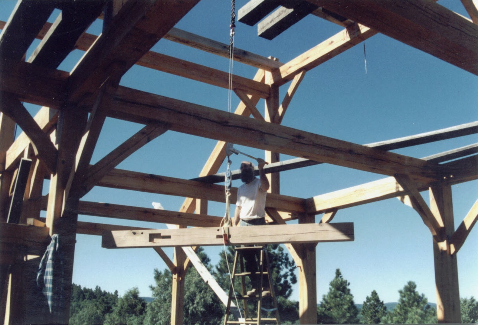
On my 47th birthday, I had one more purlin to install to finish the frame. I was disappointed that Linda was not there for this momentous event. My friend, Carl, who had been visiting on a regular basis, was aware of my mood and took it upon himself to make this occasion more noteworthy. With excellent timing, a parade of neighbors and their dogs came down the driveway to help me celebrate, champagne and all! One member of the group even brought his video recorder and later gave me a tape of the event. I was touched by Carl’s thoughtfulness and the support of my neighbors.
 
Raising the second to last timber
My photograph collection is focused on the raising of the frame because, for me, this was the most interesting and challenging part of the project. One could almost think that the finished timbers were being delivered now and then, and I took pictures of raising them! Actually, for every timber-raising event, there were several weeks of timber cutting that never made it to film. There were 268 dovetails and 140 brace tenons and their 408 associated mortises to be cut - not mention a host of other mortise and tenon joints - all as close to identical as possible and incredibly boring to document. However, this joinery is crucial to the construction of a timber framed building. I’ll discuss the time-consuming and somewhat boring process of timber joinery cutting in the chapter called “Joinery”.

Chapter 12 - Loft Framing - Phase II


Chapter 12 – Loft Framing
Phase II
Linda takes her jobs very seriously. I told her that the timbers that were sitting in drippy humid Pennsylvania needed to be turned from time to time so they would dry evenly and not get moldy. I was only half serious, since most of those timbers were much heavier than she is. She also learns very quickly. She had her favorite stick (lever) and rolled each timber regularly, kept them covered with tarps, cared for them like her children and I found them in perfect condition.
Meanwhile, Keith, my trusty sawyer was busy making oak boards. He had about six bundles of boards in his saw yard that I could have for less than a dollar a board foot. That seemed like a lot of wood, and at the time, what I would use all those boards for was only vaguely clear. I figured that there were enough boards in his pile to cover the first floor twice! Though these boards were not the best grade lumber on the planet, the price seemed right. Besides, we had to fill a flatbed with something, and keeping Keith happy was a very good idea. As I write this, I’m running out of boards and have no idea how I would have finished this house without them.
In a few weeks, I had all the timbers banded and all those boards un-stickered and re-stacked into nice tidy bundles. After two previous flatbed loading experiences, I basically knew what I was doing this time. Having learned that I was not very good at estimating timber weights, this time I had the driver take the truck to a scale the day before he was to leave and before Keith took his backhoe home. Sure enough, the load was over weight, and a few bundles of boards were left behind.
By now, Linda was excited about the idea of moving to Colorado. She had her house up for sale and knew exactly what was going with her. The children were less enthusiastic about mom moving away. I think they realized that she was serious when we parked a moving truck in the driveway and started loading the left behind boards and most of Linda’s precious stuff inside.

On July 15, 1998, Linda and I were again cruising across the country, this time in a big new moving truck. This load included all Linda’s precious stuff and even a mattress that we used as a motel room at truck stops. Most folks seem to think that that was pretty weird, but it made perfect sense to us. Once we got to Colorado, I went looking for the fellow in town with the forklift. I had to resort to the rental store, which fortunately had exactly what I needed. Unfortunately it did not come with an operator. This did not seem like a very good time to learn how to operate a forklift but it was certainly exciting. Actually it was not that hard, I’ve had a lot more trouble mastering a backhoe.
With all of our stuff either put in the place that Linda had planned for it in the apartment or stacked in the corner of the workshop under tarps, it was time to get back to work. By now it was August and if I was going to get the frame done in keeping with my chiseled in oak date of “1998”, I had to move right along. I had already done the hard part of the loft level framing, the part that seemed the highest in the air. The back half also had the advantage of joists to stand on. Compared to the open bay #1 area, this end was like working on the ground! By September 16th, the loft level was finished.
 All I have are photos of the raising technique for the back half of the loft raising that I developed after quite a bit of practice. After lifting the two queen posts and their bay beam to the loft level, I assembled and strapped together the unit along with the braces and the spline for the middle bay beam. This process insures that all of the joinery fits before the unit is lifted into place. The base of the crane, standing on runners, is attached to a first floor beam behind it with an orange ratchet strap. As the crane lifts the assembly, the post bottoms slide and catch on the post bottom blocks stopping the assembly from sliding toward the crane. Once the posts are stopped from sliding toward the crane, without the strap to hold the crane in place, jacking up the crane would simply pull the crane forward on its runners under the assembly. When the assembly was beyond half way raised, most of its weight was directed to the bottom of the posts. Because most of the weight is now off the crane, the ratchet strap can be shortened easily, pulling the crane backward on its runners and continuing to raise the assembly.
The crane runners in this raising are only 2-inch thick boards instead of the 6x8 timbers that were used for this raising in bay #1. That is because the bent beam is higher than the bay beam that the crane is attached to so the crane didn’t need to be as tall to lift the assembly. Also, in this bay, I had joists to support the center of the boards that would have bent under the weight of the crane over the open area in bay #1.
 
There are two blue ropes attached to the bay beam and the first floor framing that are tied to the right length to prevent the assembly from being pulled over too far beyond vertical. Continuing to shorten the orange ratchet strap pulled the crane backward and the assembly the rest of the way to vertical. Once the assembly was upright, the other ends of the blue ropes are attached to the first floor framing on the crane side of the assembly to guy the unit in place. The crane can then be disconnected.
Despite the fact that I carefully measured and cut the lower rafters, I raised them in opposite pairs without pegging them so that I could fractionally adjust their fit after they were in place. Since the queen posts were not pegged to the frame, but rather resting on the beams underneath them on their blocks, I could still move the queen post and beam unit in the direction of either lower rafter a bit. Once the joinery of both lower rafters were held tightly in place with straps wrapped around the first floor framing, pulling them downward, I compared the fit at the tops of the two queen posts. I made the two rafters fit the tops of the two queen posts by pulling down on one rafter and loosening the other rafter. The two queen posts could also be slightly moved to help this fitting process. I had already done this alignment process with the bent #1 and bent #2 lower rafters. After adjusting the bent #3 lower rafters, I also made sure that the tops of all of the queen posts were aligned along the axis of the frame. Making sure that all of the joinery fit together tightly, I then pegged the rafters at each end and the tops and bottoms of the stub posts. This rafter and stub post pegging locked the queen post locations on top of the beams in place. I then repeated this process for the bent #4 lower rafters.
I tried stretching a string along the tops of both sets of queen posts to check their alignment. This didn’t tell me much because the 40-foot length allowed the string to sag too much. The best I could do was sight along the outside top corners of the queen posts and assure myself that they all lined up.
Now that the rafters and queen posts were all firmly in place, I could install the purlins connecting the rafters together. The purlins for bays #1 and bay #3 are nominally 14 feet, 8 inches long and the center bay purlins are nominally 8 feet long. I, of course, measured each span before I made the purlin to get a precise fit for each purlin. All of them are 6x8 timbers with un-housed dovetails at each end. The purlins are spaced 4 feet apart, from center to center so that any standard roofing plan would work. At the time, I was thinking in terms of stress-skin panels that come in 4-foot wide sections or could span 4 feet. Each bay has six purlins connecting the lower rafters together, three on each side of the queen posts. The north center bay is slightly different; its top purlin is omitted. This difference is to provide a space for a chimney to pass through the framing.
 
The last time that Linda was here, she wondered why I was cutting off all of the peg ends. Because I was reasonably athletically inclined and knew how to use a hand saw; cutting off the peg ends was the job that I always wound up with when I worked with Ed. It was just part of the process. Linda thought that I should leave the peg ends sticking out of the frame. They would come in handy to hang stuff on! So, I quit cutting off the peg ends, except when the mallet mangled them beyond hope.

Chapter 12 - Loft Framing - Phase I


Chapter 12 – Loft Framing
Phase I
The loft framing was done in two phases. Phase I is during the seven weeks between the finishing of the first floor framing and the first of June. I then returned to Pennsylvania and it took about a month to arrange for the third and final flatbed truckload of oak timbers and boards to be delivered to Colorado. In the middle of July, Linda and I rented a moving truck, loaded it up with more furniture and followed the flatbed to Colorado. While we were together in our apartment, we re-arranged the furniture and stored the furniture that wouldn’t fit in the apartment under a tarp in the corner of the daylight basement. Phase II of the loft level raising began after Linda went home and was completed on September 16, 1998.
As usual, my documentation begins after the first steps of the project are done. I was more occupied with how I was going to safely accomplish this phase of the project than photographing the process. Perhaps I had documented enough ”oops” that I didn’t want to do it again!
My problem solving technique involves the extensive use of the process known as “sleep on it”. If the problem is complicated or new enough, this “sleep on it” process can be very long! I usually wake up with a notion of a solution to the perceived problem and spend the rest of the day fitting this solution into the existing grand plan. This often leads to another problem to sleep on, starting the process all over again. Sometimes I even resort to finding a book on the subject or asking someone who might have some ideas on the matter. In due course, a plan worth testing without any foreseeable “gotchas” evolves.
My high school English teacher required as part of the course that we keep a journal, and turn it in once a week so that he could make sure that we actually wrote something. I think his plan was to provide penmanship and authorship practice. Since high school I kept other journals from time to time that I have found useful for one reason or another later on. While building this house, I made tons of drawings and lists, took many photos, filmed several hours of what I thought were significant events, but did not write one line in a journal. I certainly wish that I had done so, now that I am trying to remember what happened several years ago! I mentioned this to Linda and her response was that I was probably so tired at the end of every day that writing in a journal was not an option. Perhaps.
Since it took several days in the basement to create the posts, beams and braces for the first section of the loft framing, I had several nights to sleep on the plan to raise them on top of the existing first floor framing. At some point, it dawned on me that, contrary to my notion that it would be just like the raising of first floor level only higher up, there was a big problem that needed to be solved. The first floor posts had a very convenient hole and peg in the deck that insured that they would be guided to and held in their proper location as they were being raised into position with guy lines as an insurance policy. All that I had on the top of the existing first floor framing was a nice slippery eight-inch wide beam to stand the posts on with a big drop-off on either side. Unlike raising a post on the deck, dancing with the post to move it to its hole was not going to work.
As I was creating the loft framing, it also occurred to me that this structure was very big. It was the same shape as the post, beam and brace structure at the ends of the first floor extensions, but the beam was twice as long. Even with this 250-pound weight difference, I could probably raise it like I did the extension ends if I could solve the post bottom-anchoring problem. On the other hand, this longer beam made it the same as the corner structure, so perhaps I could raise it like I did the corners. However, the raising of the corners had the advantage of one of the end posts already being firmly set in place. All I had to do in the corners was raise one post, set it in its deck hole, anchor it temporarily in place with guy lines and then lift and install the beam and braces in between. I could not come up with a plan that would insure that I could lift two posts into position on an 8-inch wide beam, make the beam braces stay put in these posts and make all of this stay put while I raised a 16-foot beam between them. One oops, bump or gust of wind could send these pieces crashing to the ground, or worse, through the deck and into the basement! If these raising problems were not enough to scare me to death, the fact that the only place that I would have to put my feet would be the tops of the 8-inch wide first floor beams 9 feet above the decking should have. I tried to stay focused on the physics problem and ignore the scariness of the situation.
One day, a solution to the post bottom-anchoring problem occurred to me. What I needed was a peg of sorts that would catch the bottom of the post and keep it from falling off the edge of, or sliding along the length of the beam that it was lying on as I pivoted it from horizontal to vertical. This peg of sorts was a tenon shaped rectangle with one corner cut off. The square end was inserted in a mortise in the beam where the post belonged and the cut off corner faced away from the bottom of the post with a similar mortise cut into its bottom. As the post was raised from horizontal to vertical, the block caught in the hole in the bottom of the post. The cut off corner allowed the post to pivot onto this block as it pivoted towards vertical. I made a drawing of the concept and even made a small model to test out the plan. The only way to know that this was going to work was to go for it.
I used this plan to raise the first loft post and beam assembly. First, I assembled the two posts and their beam and braces horizontally. The post bottoms were then aligned with my blocks. Several straps were attached end-to-end and stretched from the loft post and beam assembly to the far side of the frame with a come-along attached to the beam. I lifted this assembly with a pair of come alongs attached to the far side of the frame. Once the first come-along had gone from fully extended to as short as it could get, a second come-along was necessary to continue the lifting process. The second come-along was strung from one of the strap loops to another loop further back along the strap. Shortening the second come-along shortened the strap length and continued the lifting of the assembly toward vertical. Knowing how I raised the rest of the loft framing (with the crane), this method was definitely the hard way and no doubt put a lot of stress on the beam that I used to pull from, not to mention the blocks that held the post bottoms in place. As I think about this process now, I am a little amazed that this method actually worked. It does indicate the solidity of the first floor framing though.
I devised a different method to raise the second loft post, beam and brace assembly. Two 16-foot long 6x8-inch timbers were stretched across the bay. These two timbers provided a table upon which to assemble the post, beam and brace assembly. Before this assembly was raised, an orange 2-inch ratchet strap was wrapped around the posts between the brace ends and the beam mortises to hold the assembly together. The table also provided a place to put blocks under the top end of the assembly to tip the top part upward and the bottom part downward toward the loft post bottom blocks.
A come-along and several straps were attached end-to-end connecting the beam of the first post and beam assembly to the beam of the second assembly being raised. Guy ropes running from the first assembly to the first floor frame held the first assembly in place. Attaching the come-along to the beam of the first assembly provided a much better lifting angle than was available for the raising of the first assembly so the lifting process went much easier. Again, once the first come-along had gone from fully extended to as short as it could get, a second come-along was strung from one of the strap loops to another loop further back along the strap. Shortening the second come-along shortened the strap length and continued the raising of the assembly. I obviously had a great deal of faith in the strength of the first floor frame and my ropes, straps and come alongs!


 It was now May 7th and I had 24 days left before I had to leave for Pennsylvania. The next part of this project was the installation of the four half rafters that connect from the tops of the four first floor posts to the tops of the four loft post that just were raised. These four loft posts are called “queen posts”. The length of these rafters is specified in the drawings based upon geometry calculations. By now I knew that the calculated lengths of timbers and the lengths that they need to be to fit tightly might not be the same. One cause of dimensional deviations is posts that are not exactly the 8x8-inch size that is called for in the plan. Although my theory that if you cut the joinery square and assemble it tightly, the assembly will be square works pretty well, it does not account for timbers that might be bent a bit. Even tiny errors have a tendency to be magnified as you add timbers upon more timbers.
To get the exact length for each rafter, I used a stick with the rafter angles cut at each end that was exactly the geometrically correct length. I knew that this stick length would be too short because most of the posts are a bit smaller than 8 inches wide. Placing the stick between the rafters, I measured how short the stick was to fit perfectly and added that length to the stick length. With these dimensions, I retrieved four of the 14-foot long 8x10-inch timbers from the timber pile, planed and sanded them, and drew the joinery on them at both ends.
At this point, the words of my mentor rang in my ears. Having never cut a bird’s beak in Ed’s shop, I recall asking him how you cut this kind of joint. His response was that by the time I got to the cutting of this type of joint, I would know what to do! This was not the answer that I wanted to hear at the time but it did seem like a problem that was really far in the future, so I did not worry about it much. Now was the time to worry about it! I used the end of my longest timber and added another bird’s beak drawing to the spare wood at the end of the timber. I used a post cutoff to create the mortise that was at the tops of the outside posts and another post cutoff to create the mortise that was at the tops of the queen posts. This practice bird’s beak joint came out just fine and fit fine in my model of the post top too. Just to be on the safe side, I cut a practice top end of the rafter as well and it too fit the model of the queen post top. Ed was right, the practice of the last few years made it clear how to cut this fancy joint. I cut off this practice bird’s beak joint and proceeded to cut the four rafters that fit up in the frame perfectly. We still have that cutoff bird’s beak model; I’d like to think that someone would find it fascinating and ask me about it, but mostly, we use it to weigh down plastic lawn chairs to keep them from blowing away in the spring winds! Actually, there are a bunch of these practice joinery stubs lying about the house; they make pretty good doorstops and book ends too.
As usual, the video record is of the raising of the second rafter with the first rafter already in place. There is also one more action packed video documenting the loft framing, Phase I. The beginning of this video is of the raising of the second loft bent beam. Although the background scenery is better because the camera is one story higher, the action is not much different than the taped raising of beams on the first floor.
Once I got to the loft framing, my new, improved gin pole became useful. The original gin pole was a 10-foot long 2x6-inch board. The new pole is 18 feet long by mortising and bolting another 10-foot long 2x8-inch board to the original pole. Though unwieldy, this pole was invaluable throughout the rest of the project.
The above story of the raising of the rafters skips over an important part of the project, the timber elevator. To raise the roof structure, each timber had to somehow get from the basement workshop to the first floor and up to the loft level. I had lots of practice getting timbers to the first floor. Fortunately, the frame structure provided a way to raise them to the loft level. I use the word “fortunately” because the open (no joists in the way) west part of the frame was designed that way simply to provide open space above the dining room and living room areas. Conveniently, the space in the center of bay #1 was big enough for a 16-foot long timber to fit through the opening crosswise. The center opening is 8 feet wide and 14 feet, 8 inches long, making the cross distance of the opening 16 feet, 8 inches long. The rough timbers that I used for scaffolding barely fit through this opening, but the finished timbers fit through this opening easily. With this handy coincidence in mind and while I had the crane situated in this area, I lifted two 16-foot long 6x8 timbers to lay across the top of the bay #1 loft structure that I had just built. After strapping the ends to the bent beams, I wrapped a chain around the center of the timber that I made sure was in the center of the opening and left the end hook of the chain hanging down far enough that I could reach it from loft scaffolding boards without a ladder.
Leaving one timber up there would have been enough to create the elevator that I had in mind. However, I was contemplating that eventually I would need to raise two king posts and the peak purlin above this timber. I would need at least two timbers up there just to stand reasonably comfortably up at that level - 18 feet above the deck - in the wind - with nothing to hold on to. I was not at all comfortable with this prospect, but I decided that I better get used to the idea. In fact, at this point, I had no notion of how I was going to raise the king posts and peak purlin and, for the moment, avoided wandering about on top of these timbers any more than necessary!
It was time to suspend the loft framing project and head to Pennsylvania once again. I always drove my truck and took different routes back and forth. Flying long distances to get somewhere quickly is not for me. The views from an airplane are certainly unique, but I would much rather see and experience the world from ground level.

Chapter 11 - First Floor Framing - Phase III


Chapter 11 – First Floor Framing
Phase III
The three phases of the framing of the first floor are more based on my mental picture of how to raise the frame than any aspect of the frame itself. I envisioned a central box as a sort of foundation, something good and solid to build upon and use as a sort of central crane. The four extensions from the central box are arms, firmly attached to this foundation, that extend its reach to the edges of a new box.  The corners are simply connections of the extensions to form a new and larger box. In theory, one could continue this process, outward to any size box. The final frame, if one doesn’t contemplate the splines, looks just like a bent raised timber frame structure. Once I had found a way to use the tools and materials that I had at hand, the three phases of construction were simply repetitions of the previous process incorporating small improvements that I discovered either by plan or by accident. The framing of the first floor was practice for the same process, another story upward in the loft, just as the basement was practice for the first floor. While I was building the basement, I kept in mind that the first floor would have no solid concrete wall to rely on. While I was building the first floor, I kept in mind that the loft would have no floor to stand on. As for the peak, I assumed that by the time I got there, the practice in the basement, first floor and the loft would provide all of the knowledge and skills that I would need.
The winter of 1997 was a vacation from Colorado! Our first grandchild was born and a flock of birthdays and holidays were celebrated. I made plans and lists, packed things that I wanted to have in Colorado, visited everyone I knew in Pennsylvania, made sure that Keith knew what timbers I needed him to cut and worried about the tarp and apartment in Colorado.
In February of 1998, Linda and I took a vacation to Colorado. When we got there, the tarp was still firmly in place and the apartment was just as I had left it. However, finding that the cistern was empty, I knew that a leak had developed. I had the solid PVC connection replaced with a rubber connection to solve this problem. No matter how firmly a cistern is planted in the ground, the process of filling it causes it to move enough to break a solid connection. Once our vacation was over, Linda went back to her job in Pennsylvania and I got back to my job in Colorado.
I started the framing of the corners with the southeast corner of the house, the kitchen, and then the northeast corner, the bedroom. This seemed like a good plan because these two corners were only a couple of feet off the ground. I figured that the practice I would gain near ground level would come in handy when I got to the west side corners whose edges were ten feet off the ground. I tried to make sure that the building process did not require me to step off the decking and onto the ground since the western corner posts had no ground to step off onto!
The raising of corner framing was very similar to the raising of the extensions from the central box. The existing attachment points for the beams (the extensions) had splines on which to rest one end of the beam while the corner post was leaned outward far enough (about four inches) for the beam tenons to be inserted into the post mortises. I now knew that the holes in the decking in which the post was inserted worked very well preventing the bottom of the post from moving. The only trick was to keep from tipping the post out too far. To make sure that this didn’t happen, three ropes were attached to the top of the post, two to the nice solid extension framing and one away from the corner attached to some heavy object, such as my truck. This third rope should be long enough so that if the other two ropes failed or the solid extension for some reason fell down, the falling post would not hit the truck! All of these ropes were tied with taut-line hitches so that the tension on any or all of them could be adjusted as necessary to tilt the post and bring it back into vertical.
I never did come up with a way to gracefully raise a single post without just picking up the end and tilting it into its deck hole. Sometimes, I didn’t quite get it in the hole and did a little dance with it. I did however carefully measure the lengths of the two ropes attached to the top of the post so that once I lifted the post upright; the two ropes would keep it from falling over in the other direction. The third rope was also already attached at the top of the post so that I could quickly attach it to a heavy object. With the length of the first two ropes carefully adjusted, pulling on the third rope would not pull the post over. The 10-foot length of the posts was also handy. I could attach these three ropes to the top foot of the posts and they would not interfere with the raising of the beams since all of the beams attached at the 8-foot high level of the post.
This phase also took longer because the parts were not precut, but rather, cut in the basement workshop, as I needed them. As I expected, this cut and assemble method went much better. The joinery was cut and assembled within days instead of months and did not have the chance to change shape. This method also resulted in my day-to-day projects changing so boredom did not set in, but the time between repeating the process was short enough that I did not forget what I had done before. As before, when the weather was obnoxious (which is not very often here in paradise) I simply turned my attention to improving the nice warm and comfortable apartment.
I should mention that there were also the more mundane, day-to-day projects going on as well, such as making meals, grocery shopping, washing clothes at the laundromat (where there was a phone to call Linda), braiding a rug and visiting with curious neighbors that stopped by to chat. My most frequent visitor was Carl, who was the self-appointed “make-sure-that-Michael-hasn’t-killed-himself” visitor. One bright sunny afternoon, I was in the process of raising the east beam of the bedroom wall. Carl drove in the driveway and stopped his truck within a few feet of the edge of the house. He sat in his truck while we chatted, and at some point I asked him if he wanted to help. “Oh no, if I help, then you won’t be able to say that you built this yourself!”  That was true, and I didn’t really want any help anyway. Carl is also the person who, after the basement was covered and knew what the rest of the plan entailed, suggested that I cover the deck with dirt and plant grass. “This apartment is plenty big for just you and Linda!” That too, was true, but I didn’t listen to that advice either.
In todays video, the bedroom corner framing will be raised. The east side beam on the sawhorses in the workshop will be raised first. The beam for the north side is on the cart, on its way up the hill. I need to cut the brace mortises in the two already raised extension posts. This is the hard way to cut brace mortises and not a good plan. With the brace mortises cut and the post hole in the deck revealed, I am ready to raise the beams. The north beam is raised into position with the right side brace tenon in its beam mortise and the beam tenon in its post mortise. The left side of the beam is in contact with the post and ready to slide down into the housing and onto the brace tenon and post spline. The close-up shows the beam spline mortise that will be lowered onto the post spline. My initials are in the post housing. Slowly lowering the crane arm, the left side of the beam slides down into position. With the beam lowered into position, another come-along pulls the assembly tightly together. Next, the summer beam that drops in the dovetailed mortise in the east beam is installed.


In the daylight basement shop, twelve 6x 8 joists were cut to length and dovetails carved at each end. Using the crane, they were lifted above the beams and lowered into their dovetailed mortises.


The raising of the northwest and southwest corners was done next. The procedure was the same as the northeast corner above, except that there are no joists. Not having anywhere to stand outside the edge of the frame proved not to be the problem that I expected, it was something different – naturally – it’s always something. Again, I didn’t have the foresight to pre-drill the peg holes. To be more generous to myself, it seemed like a good idea at the time to drill and peg the beams after they were raised and tightly in place. Before describing this part of the raising, the post joinery should be explained.
This frame design features all of the top surfaces of the horizontal beams on the first floor level at the 8-foot 10-inch height above the floor. Having never designed a timber framed building before, and certainly not experienced enough to have a firm grasp of all the details; I was concerned about having the entire loft floor surface at the same level across two bays and having beams at that level around the edge of the loft level as well. It seemed to me at the time that this requirement could not be satisfied by the traditional framing methods. In hindsight, this requirement was pretty silly and traditional framing methods would have worked just fine. I seem to have invented a problem and then invented a solution, neither of which was necessary! On the bright side, my solution worked very well and looks beautiful!
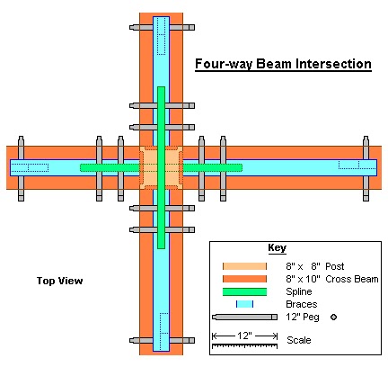
Traditional timber framing does not allow for four beams to meet a post at the same height without using posts that are very wide at the top. The reason that a large post top is needed is that once two of the beams have been pegged on either side of a square post, the first two beams have covered the pegging sites for the tenons of the other two beams. The joining of four beams at a post without using a very large post top is accomplished in this frame design with the use of two splines that cross within the post, one spline along the top of the two bent beams running one direction and one spline along the bottom of the two summer beams running the other direction. In this fashion the splines serve as four tenons that are joined to the beams rather than the post. In fact the spline is not pegged to the post at all but floats inside its slot. When I assembled the central stairwell box, the eight splines (two at each corner) were pegged to the beams leaving the other end of the splines sticking out to receive the eight extension beams that were raised later. What was actually holding the free standing central stairwell box together was the sixteen braces that were pegged to the four top beams and the four corner posts. The four posts between the four corner posts are decorative, with the exception that two of them are used to support the landing for the stairway to the loft.

When three beams meet at a post at the same level, only one spline is used. This configuration occurs in eight locations of this frame design, once at each end of the bent #2 and bent #3 first floor bent beams, and once at the ends of each of the four summer beams that extend from the central stairwell box to the outside edge of the frame; in other words, at the ends of the extensions of the central stairwell box. The alternative to this spline technique would be to have tenons at the ends of both 6x10-inch bay beams at the outside of the frame. Both of these tenons would need to be pegged from the outside of the post with short pegs to avoid driving the pegs into the backside of the bent beam housing. The outside bay beams are 6 inches wide meeting an 8-inch wide post. This leaves two inches of exposed post for the pegging of the perpendicular bent beam tenon. This is not a problem as long as the beam is pegged before one or the other bay beams are set in place. The spline is located at the lower edges of the bay beams with the top half of the beams housed into the post. The spline mortise is 4 inches deep, 1 1/2 inches wide and 11 inches long. The spline itself is 5 inches wide, leaving 1 inch exposed below the bottom of the beam. This exposure not only looks nicer, but it increases the amount of wood in the spline. With an 8-inch post, the total spline mortise is 30 inches long. I cut the splines about 1/4-inch short to allow for post shrinkage and to insure that the spline would not interfere with the assembly of the outside corners of the frame. The three braces are three different sizes, as they are in the four-way intersection, 24 inches in bay #2 and between the summer beams, 30 inches in bay #1 and bay #3 and 36 inches in the bents. This allows the three brace mortises to be at different locations on the post. If two or all three braces were the same size, two or three mortises would be at the same point on the post on two or three sides, dramatically weakening the post.
 

I pegged the spline to the 6x10-inch bay beams in the extension sections when they were raised, again leaving the other end of the splines sticking out to receive the eight beams that connect to the four corner posts that were raised later. Since I pegged the braces in the extension section, the two posts were locked in place by the braces. Then, when I raised the corners, I wrapped straps around the corner post and the two extension posts and pulled the corner post inward creating a tight fit of the beams attached to the corner post and resting on the un-pegged splines. Once the two beams were tight between the two extension posts and the corner post, I pegged the beam tenons in the corner post. Then the two splines extending from the extension posts were pegged to the two beams. Pegging the four braces in place locked the entire assembly together. 
The four two-way intersections at the corners of the frame do not use a spline. The 8x10-inch bent beam that meets the 8x8-inch corner post is pegged just as the bent beams are for the three-way intersection. The 6x10-inch bay beam, instead of being splined, is also pegged to the post. The bay beam mortise must also be pegged to the post from the outside of the frame. Since this peg will hit the housing of the bent beam if driven in too far, I cut it to the right length before I pounded it in. The lower peg for the bay beam brace must also be driven in from the outside of the frame since its position is very close to the side of the bent beam brace.
On April 12, 1998, the first floor framing was done. It had taken two months to finishing framing the four corners starting from the finished central plus assembly. Before I assembled any parts of the frame, I applied tung oil to the joinery areas, including inside the joints. I quickly learned to avoid oiling the center of gravity areas of the timber that I used to wrap straps around. The tung oil makes the timbers very slippery and the strap slides around much too easily. Once a section of the framing was pegged, I oiled the rest of the section.


Oiling the timbers also exaggerated the color differences of the three species of oak timbers that I was working with. Most of the timbers were made of red oak that, when oiled, turn golden brown. The rest of the timbers were mostly white oak with an occasional pin oak. It is hard to tell what kind of oak a weathered timber is, they are all kind of gray looking. It was easy to tell when I started working with a white oak timber, white oak was much heavier than red oak and it was as hard as a rock. The color of oiled white oak varies from almost white to chocolate brown, even within the same timber. The pin oak timbers were also easy to differentiate once I started working with, them they smelled bad. These pin oak timbers have the most grain character and large color variations within the timber.
As time has passed, to the average person, all three kinds of oak timbers all look the same golden brown. To me, after having examined each timber for its suitability for a particular frame member, moved it from the storage pile to the sawhorses to the raising site and then lifted it into place, planed, sanded and carved joinery into it, I know each timber intimately. To me, each timber is a unique oak tree that I know very well and am proud to have as a part of my home.